Seebeck Effect
The Seebeck effect creates a voltage in conductors or semiconductor when subjected to a temperature gradient, i.e. when one side of the material is warmer than another. This effect enables thermoelectric devices which can measure temperature and generate electricity from waste heat.
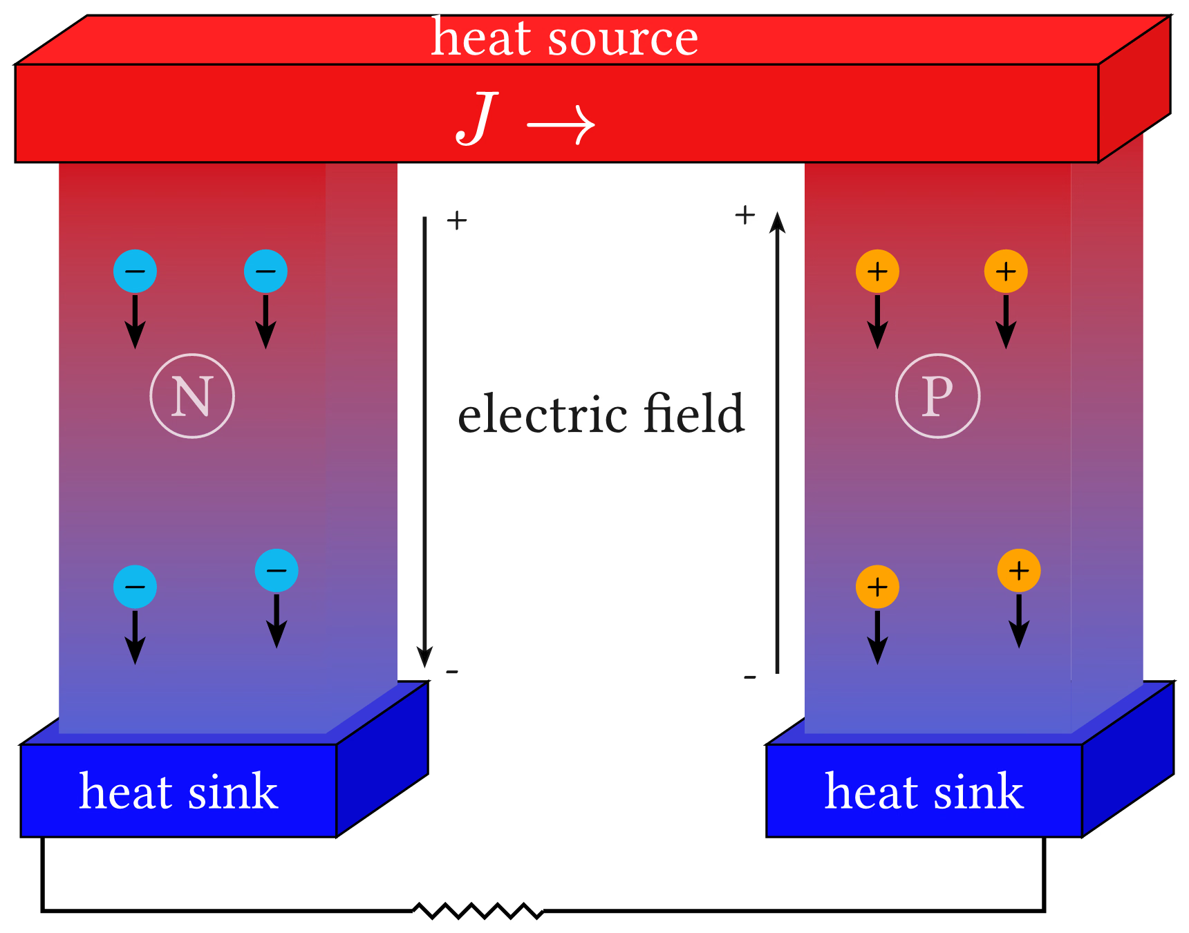
Download
Code
seebeck-effect.typ (253 lines)
#import "@preview/cetz:0.5.2": canvas, decorations, draw
#import draw: circle, content, line, on-layer, rect

#set page(width: auto, height: auto, margin: 4pt, fill: none)
#set text(size: 12pt)

#let dy = 0.45
#let sink-dx = 0.84
#let sink-dy = 0.58
#let bar-dx = 0.66
#let pillar-dx = 0.66
#let edge-stroke = (paint: black, thickness: 0.6pt)
#let circuit-stroke = (paint: black, thickness: 1.1pt)
#let circuit-mark = (symbol: "stealth", fill: black, scale: 0.5, shorten-to: none)
#let field-color = black.transparentize(10%)
#let field-stroke = (paint: field-color, thickness: 1.0pt)
#let field-mark = (end: "stealth", fill: field-color, scale: 0.55)

#let sink-blue = rgb("#0b0bff")
#let sink-side-blue = rgb("#0606cf")
#let pillar-grad = gradient.linear(
  rgb("#d20a17"),
  rgb("#5660d4"),
  angle: 90deg,
)
#let bar-red = rgb("#ef1313")
#let bar-side-red = rgb("#de1313")
#let bar-top-red = rgb("#ff2222")
#let n-color = rgb("#11b7ef")
#let p-color = rgb("#ffa300")
#let bar-x0 = 1.0
#let bar-y0 = 7.0
#let bar-w = 9.95
#let bar-h = 0.9

#let draw-prism(x0, y0, w, h, depth-x, front-fill, right-fill, top-fill, stroke, depth-y: dy) = {
  rect((x0, y0), (x0 + w, y0 + h), fill: front-fill, stroke: stroke)
  line(
    (x0 + w, y0),
    (x0 + w + depth-x, y0 + depth-y),
    (x0 + w + depth-x, y0 + h + depth-y),
    (x0 + w, y0 + h),
    close: true,
    fill: right-fill,
    stroke: stroke,
  )
  line(
    (x0, y0 + h),
    (x0 + w, y0 + h),
    (x0 + w + depth-x, y0 + h + depth-y),
    (x0 + depth-x, y0 + h + depth-y),
    close: true,
    fill: top-fill,
    stroke: stroke,
  )
}

#let charge-marker(x, y, sign: $+$, fill: p-color) = {
  circle((x, y), radius: 0.2, fill: fill, stroke: none)
  content(
    (x, y + 0.03),
    text(size: 12pt, weight: "light", fill: black)[#sign],
    anchor: "center",
  )
  line(
    (x, y - 0.22),
    (x, y - 0.72),
    stroke: (paint: black, thickness: 1.3pt),
    mark: (end: "stealth", fill: black, scale: 0.7),
  )
}

#let sink-block(x0, y0, w: 2.9, h: 0.85) = {
  draw-prism(
    x0,
    y0,
    w,
    h,
    sink-dx,
    sink-blue,
    sink-side-blue,
    sink-side-blue.lighten(20%),
    edge-stroke,
    depth-y: sink-dy,
  )
  content(
    (x0 + w / 2, y0 + h / 2),
    text(size: 14pt, fill: white)[heat sink],
    anchor: "center",
  )
}

#let pillar-w = 2.45
#let pillar-h = 5.35

#let pillar-block(x0, y0, w: pillar-w, h: pillar-h, label: [N]) = {
  rect((x0, y0), (x0 + w, y0 + h), fill: pillar-grad, stroke: none)
  line(
    (x0 + w, y0),
    (x0 + w + pillar-dx, y0 + dy),
    (x0 + w + pillar-dx, y0 + h + dy),
    (x0 + w, y0 + h),
    close: true,
    fill: pillar-grad,
    stroke: none,
  )
  circle((x0 + w / 2, y0 + h * 0.58), radius: 0.38, stroke: (
    paint: white.transparentize(25%),
    thickness: 0.7pt,
  ))
  content(
    (x0 + w / 2, y0 + h * 0.58),
    text(size: 16pt, fill: white.transparentize(25%))[#label],
    anchor: "center",
  )
}

#let field-arrow-with-polarity(x, y-start, y-end, top-label, bottom-label, label-side) = {
  line((x, y-start), (x, y-end), stroke: field-stroke, mark: field-mark)
  let x-offset = if label-side == "west" { 0.18 } else { -0.18 }
  content(
    (x + x-offset, y-start),
    text(size: 12pt, fill: field-color)[#top-label],
    anchor: label-side,
  )
  content(
    (x + x-offset, y-end),
    text(size: 12pt, fill: field-color)[#bottom-label],
    anchor: label-side,
  )
}

#let draw-circuit-leg(..pts) = {
  line(..pts, stroke: circuit-stroke)
}

#canvas({
  let left-sink-x = 1.05
  let right-sink-x = 7.9
  let sink-y = 0.8
  let pillar-y = sink-y + 0.95
  let left-pillar-x = left-sink-x + 0.35
  let right-pillar-x = right-sink-x + 0.35

  // Left (N) pillar and sink
  sink-block(left-sink-x, sink-y)
  pillar-block(left-pillar-x, pillar-y, label: [N])
  let left-field-x = left-pillar-x + pillar-w + pillar-dx + 0.25
  field-arrow-with-polarity(
    left-field-x,
    pillar-y + pillar-h - 0.6,
    pillar-y + 0.6,
    [+],
    [-],
    "west",
  )
  for (dx-offset, dy-offset) in (
    (1.05, 5.2),
    (2.25, 5.2),
    (1.05, 2.3),
    (2.35, 2.45),
  ) {
    charge-marker(left-sink-x + dx-offset, sink-y + dy-offset, sign: [−], fill: n-color)
  }

  // Right (P) pillar and sink
  sink-block(right-sink-x, sink-y)
  pillar-block(right-pillar-x, pillar-y, label: [P])
  let right-field-x = right-pillar-x - 0.25
  field-arrow-with-polarity(
    right-field-x,
    pillar-y + 0.55,
    pillar-y + pillar-h - 0.55,
    [-],
    [+],
    "east",
  )
  content(
    ((left-field-x + right-field-x) / 2, pillar-y + pillar-h * 0.55),
    text(size: 15pt, fill: field-color)[electric field],
    anchor: "center",
  )
  for (dx-offset, dy-offset) in (
    (1.02, 5.2),
    (2.2, 5.2),
    (1.02, 2.3),
    (2.32, 2.45),
  ) {
    charge-marker(right-sink-x + dx-offset, sink-y + dy-offset, sign: [+], fill: p-color)
  }

  // Top heat source bar (foreground so it occludes pillars/charges)
  on-layer(20, {
    draw-prism(
      bar-x0,
      bar-y0,
      bar-w,
      bar-h,
      bar-dx,
      bar-red,
      bar-side-red,
      bar-top-red,
      edge-stroke,
    )
    content(
      (6.05, 8.16),
      text(size: 15pt, fill: white)[heat source],
      anchor: "center",
    )
    content(
      (5.68, 7.4),
      text(size: 20pt, fill: white)[$J arrow.r$],
      anchor: "center",
    )
  })

  // Bottom wire closing the electric circuit with central resistor zig-zag.
  let wire-y = 0.12
  let left-wire-x = left-sink-x + 0.2
  let right-wire-x = right-sink-x + 2.55
  let zig-right-x = 5.85
  let zig-left-x = 4.65

  // Right-angle segments.
  draw-circuit-leg(
    (right-wire-x, sink-y),
    (right-wire-x, wire-y),
    (zig-right-x, wire-y),
  )
  draw-circuit-leg(
    (zig-left-x, wire-y),
    (left-wire-x, wire-y),
    (left-wire-x, sink-y),
  )
  // Center resistor as a decorated zigzag, with multiple arrow tips on the same path.
  decorations.zigzag(
    line(
      (zig-right-x, wire-y),
      (zig-left-x, wire-y),
      stroke: circuit-stroke,
      mark: (
        end: (
          (pos: 20%, ..circuit-mark),
          (pos: 50%, ..circuit-mark),
          (pos: 80%, ..circuit-mark),
        ),
      ),
    ),
    amplitude: 0.12,
    segment-length: 0.2,
  )
})